
Product and technology development
We develop products for vehicle manufacturers (OEMs) and Tier 1 suppliers. With process simulations, we avoid problems in production.
From concept to tested prototype
We develop mechanical parts and assemblies in aluminium, steel, sheet metal and plastics. We carry out most of the project ourselves, so you have one point of contact and less coordination:
- Communication with the client and definition of requirements
- 3D modelling of concepts and variants
- Computer simulations and design validation
- Technical drawings and documentation
- Prototype manufacturing and testing – see Prototypes and Measurement
We also develop products, tools and equipment for other industrial sectors. On request, we manage the development project and advise on process optimisation.
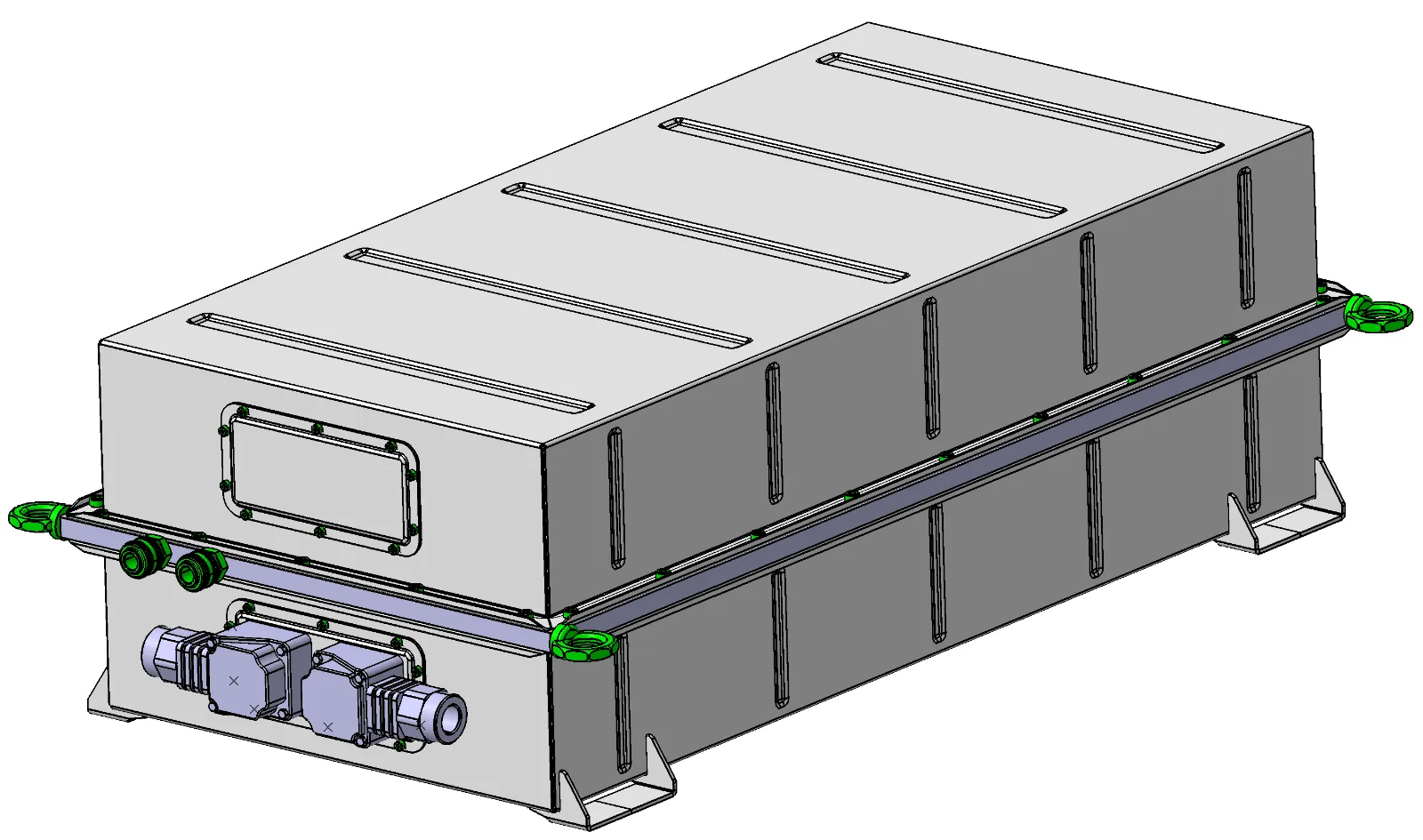
Water-cooled battery pack
The development of a battery pack for a marine application included the concept, 3D design with documentation and simulations, with a focus on structural and thermal requirements.
Oscillating cutter
From drive and blade guidance design to strength analyses of the key components.
Automotive component development
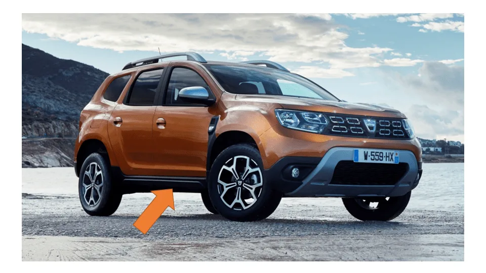
We work closely with TIER1 suppliers and vehicle manufacturers (OEMs). We take care of concept definition, detailed 3D modelling, simulations, cost control during development, optimisation, technical documentation and Design-FMEA, as well as prototype manufacturing.
We have experience in developing engine and accessory brackets, bonnet and door hinges, brake pedals, roof rails, structural parts, rubber parts and interior and exterior plastic parts.
Technology-driven development
We define the product together with its manufacturing technology. The very first part is manufacturable, cost-effective and free of surprises in production. We also develop production tools (forming tools and welding and checking fixtures – see Production equipment).
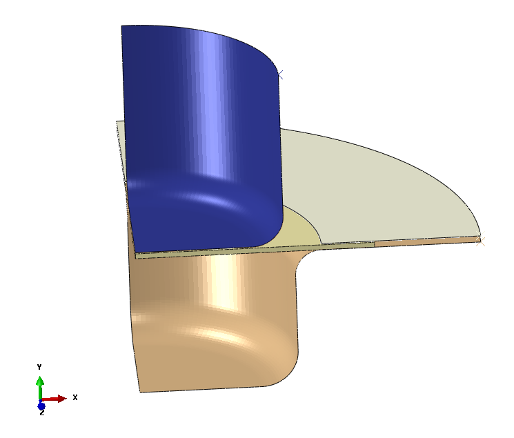
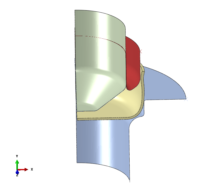
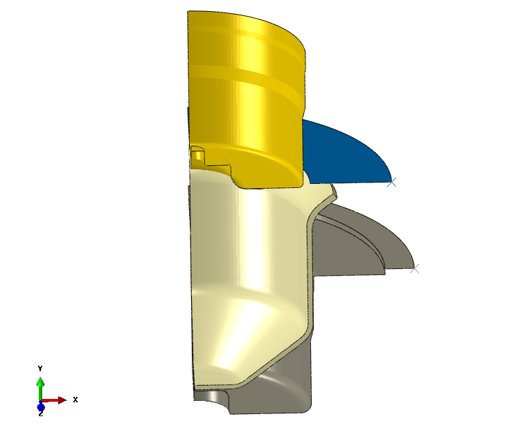
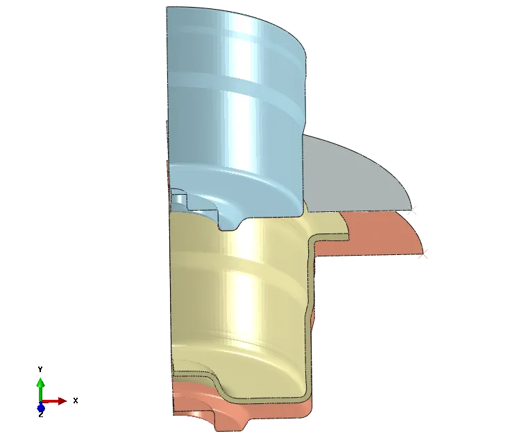
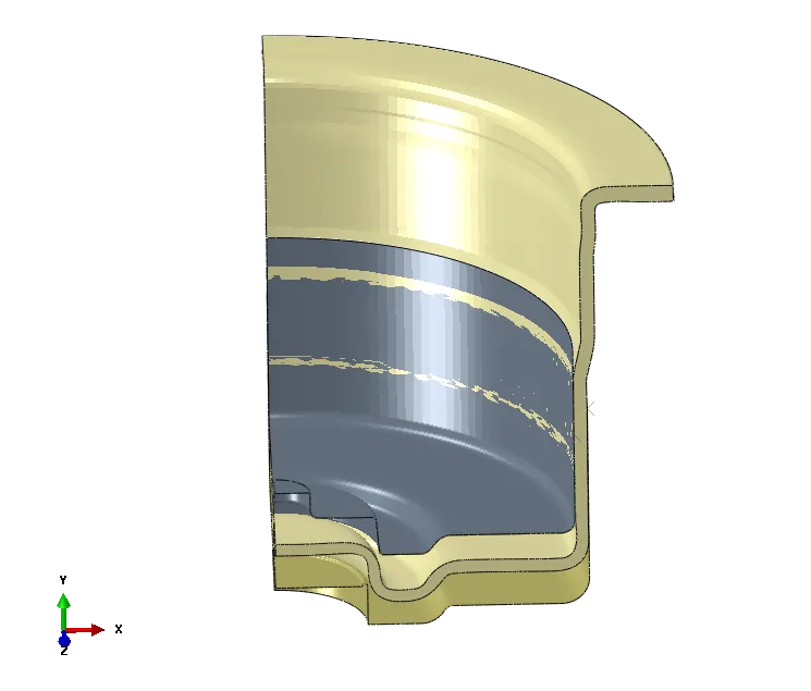
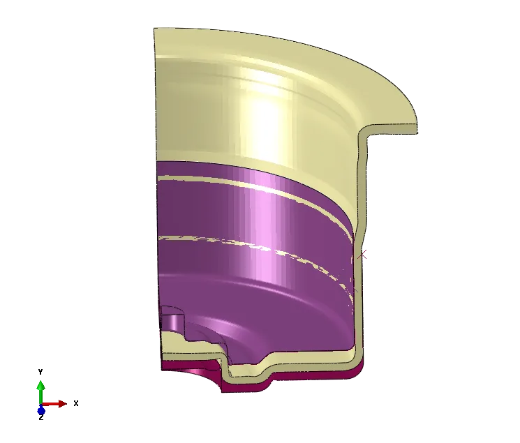
Stage-by-stage deep drawing process development
We define the sequence of forming steps and verify it with simulations. Before any tools are made, we confirm that the part can be manufactured.
Production process optimisation
Cracks, out-of-tolerance dimensions, too much scrap? We use simulations to find the cause and eliminate it.
- Problem analysis and current-state review
- Process simulation and root-cause search
- Proposed changes and simulation of the improved state
- Practical trial
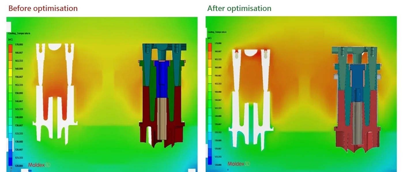
No cracks, no warpage
In powder injection moulding (PIM) we optimised the geometry, tolerances and material of the inserts. Before optimisation the parts were distorted and cracked due to residual stresses; after optimisation they are geometrically compliant.
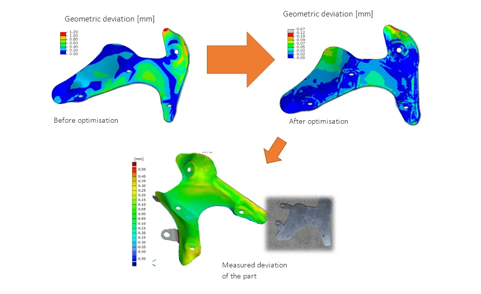
Tool and blank optimisation
By optimising the tool and blank geometry simultaneously, we reduced deviations from the nominal geometry. The image shows the deviations before and after optimisation and a comparison with the measured part.
Selected development examples
More projects from product and process development.
Show examples (5)Hide examples
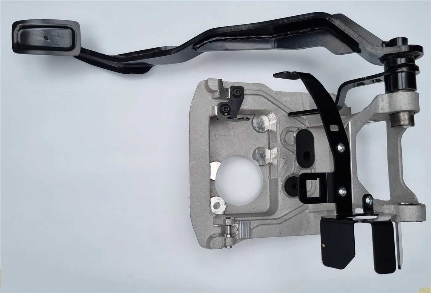
Pedal box
Pedal box: concept, cost control during development, drawings, static validation (10+ load cases) and prototype manufacturing.
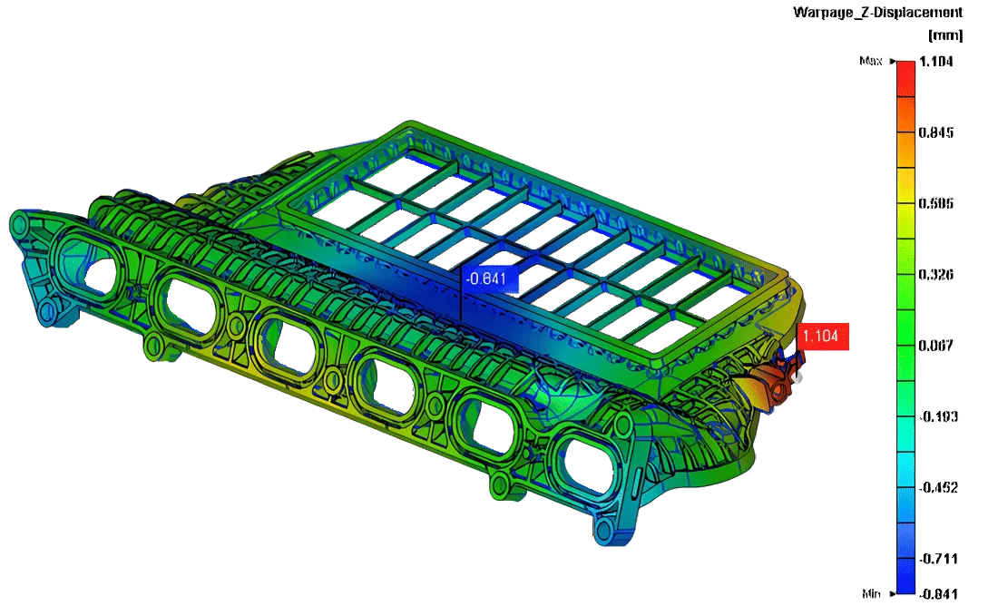
Warpage compensation
Simulation of warpage of a moulded part and compensation of the mould geometry.
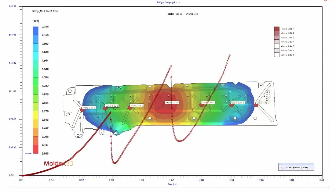
Cascade injection moulding of a large part
Optimisation of the number and positions of gates, the opening sequence and the geometry of a 1.6 mm thick part. We achieved a cheaper mould and a lower required clamping force.
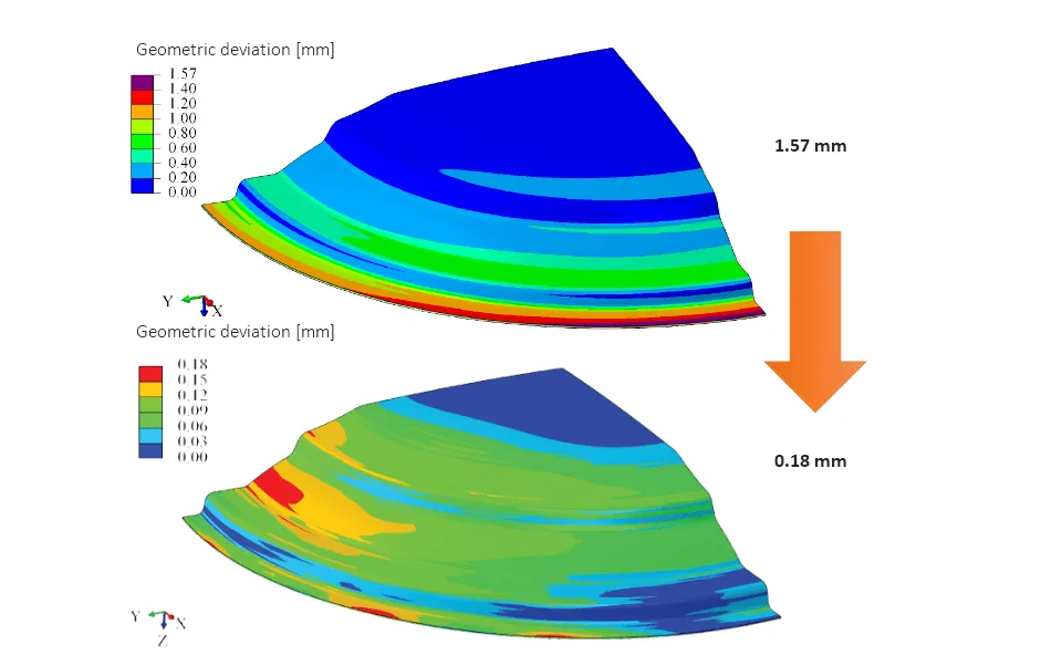
Tool geometry optimisation
By optimising the geometry of the forming tool, we reduced the part deviation by 90%.
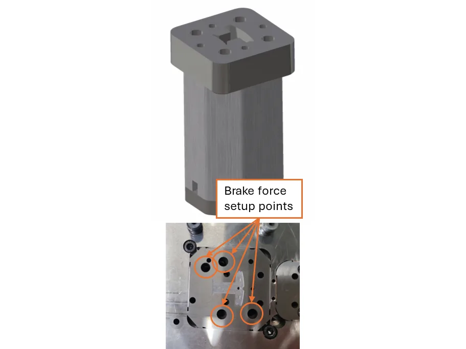
Brake module for interlocking laminations
A compact brake module for interlocking lamination stamping tools. The brake force of each module is adjusted with a screw – without removing the tool or lengthy corrections. The stack stays stable even when dimensions fluctuate. The solution suits T-segments, circular laminations and rotary interlocking. We provide analysis, design, finite element verification and manufacturing of modules.
Our customers and partners






















Have a technical challenge?
Describe it in a few sentences – we will propose an approach, a timeline and a cost estimate.